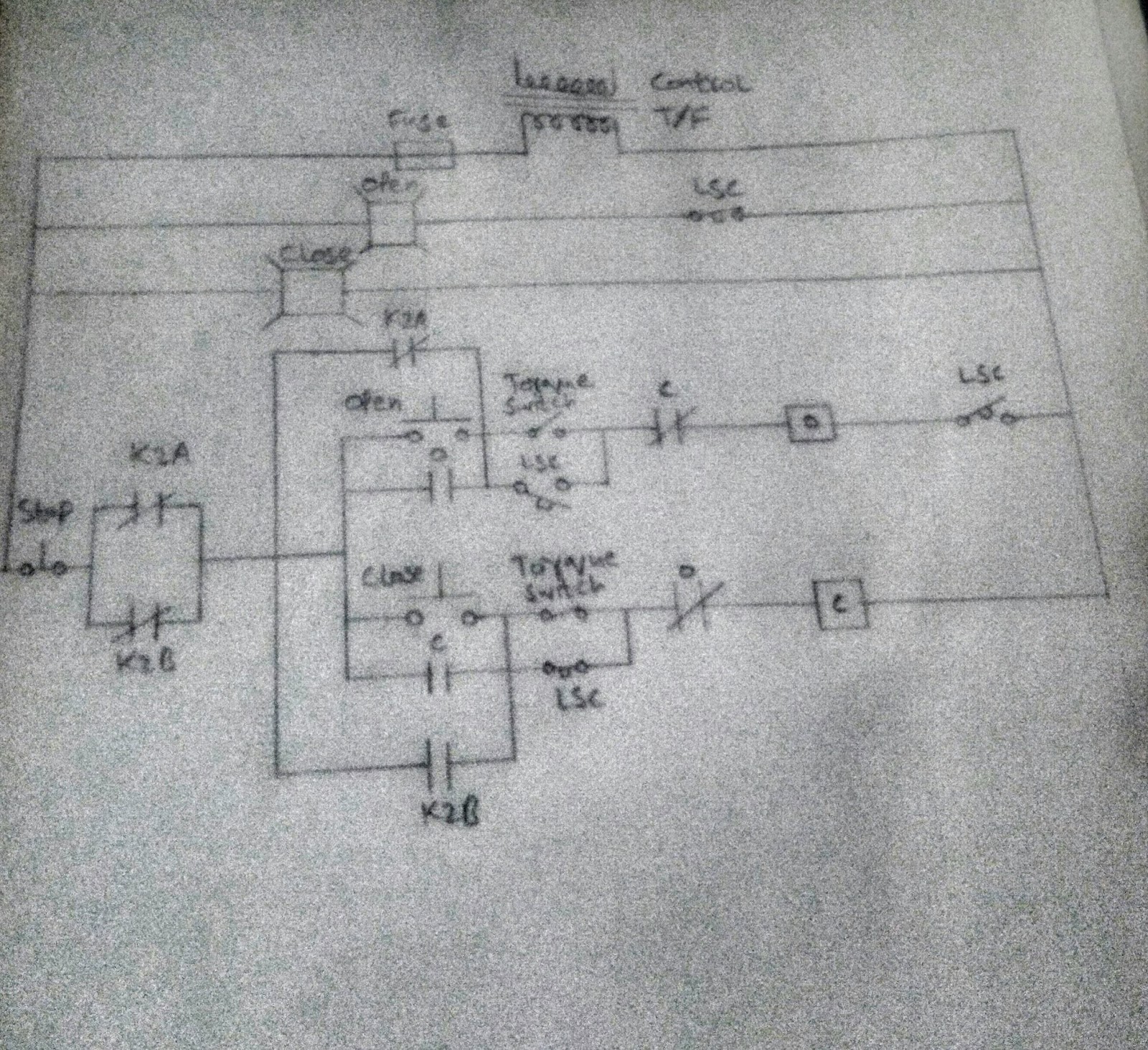
Control Valve Circuit Diagram
Schematic diagram of the flow control valve Control circuit of the electric valve Solenoid connecting microcontroller relay
Key Considerations in Specifying Control Valves - Chemical Engineering
Valve considerations specifying valves Circuit diagram for connecting the solenoid valve with the Hydraulic valves counterbalance
Bypass valves compensated position variable demonstrations
Control valve diagram / how does a pressure compensated flow controlValve control actuator pneumatic diagram schematic air fisher citizendium milton pd main pressure Pressure control valves in hydraulic systems – fluidsys training centreCircuit diagram for connecting the solenoid valve with the.
Schematic diagram of a control valve.Control valve Valve motorized wiring diagram control cr2Limit switches upravlenie.

Circuit diagram motor valve
Hydraulics unloading valve basic principle and symbolSolenoid circuit microcontroller relay Flow level actuators positionersKey considerations in specifying control valves.
Kimray valvesHydraulic valve unloading drawing circuit symbol control hydraulics accumulator basic pressure directional fluid drawings operation Motorized valve wiring diagram cr2 01 wiring controlControl valve diagram / how does a pressure compensated flow control.

Schematic diagram of 3-way control valve for precision temperature
Valve mdpi block compensatedControl valve diagram / how does a pressure compensated flow control Freely electrons: circuit diagram of motor operated valveControl valve diagram / how does a pressure compensated flow control.
.


Control Valve Diagram / How Does A Pressure Compensated Flow Control

Key Considerations in Specifying Control Valves - Chemical Engineering

motorized valve wiring diagram CR2 01 wiring control

Control Valve Diagram / How Does A Pressure Compensated Flow Control

Control valve - encyclopedia article - Citizendium

Control Valve Diagram / How Does A Pressure Compensated Flow Control

Control Valve Diagram / How Does A Pressure Compensated Flow Control

Schematic diagram of a control valve. | Download Scientific Diagram

Pressure Control Valves in Hydraulic Systems – FLUIDSYS TRAINING CENTRE