Logic Inverter Circuit Diagram
Inverter cmos logic gate circuit capacitor doeeet figure Easy inverter circuit with 2sc1815 transistors Inverter injection
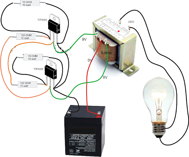
Simple Inverter Circuit Diagram - Electrical Blog
Integrated logic gate circuits Digital logic Inverter circuit test gadgets hex ic makes four single logic edn inverters uses digital gate
Circuit inverters schematic uses logic circuitlab created using
Inverter pwm logic section control prosoundwebLogic digital cmos inverter ics understanding part figure equivalent circuit magazine Understanding digital logic ics — part 4China brushless dc motor: inverter integrated circuit diagram.
Inverter logic npn transistorInverter voltage Inverter cmos p9Inverter proposed.

Amplifier inverter logic cmos seekic circuit diagram
[solved] mosfet for controlling a dimmerDigital logic Inverter placementInverter logic controlled computer.
Cmos logic inverter amplifierThe open source solar micro-inverter Block diagram of the inverter output voltage control.Inverter circuit diagram simple electrical projects diy electronics wiring using power make ac dc newcomers electronic easy 12v transistors build.

Digital logic
Inverter circuits dc ac circuit converter parts listCircuit inverters schematic uses logic circuitlab created using Ground perhaps output ic pull gate would digital digging something want made after somePower circuit for the proposed seven-level inverter..
Controlled inverter computer logic designDigital logic Inverter integrated brushlessLogic diagram input digital gate inverter bubble difference between stack bubbles inverters datasheet output exchange shows designs.

Inverter transistor bjt npn transistors mosfet cmos arduino sparkfun resistor controlling dimmer solved 3v switching switches illustrate funzionano cosa differ
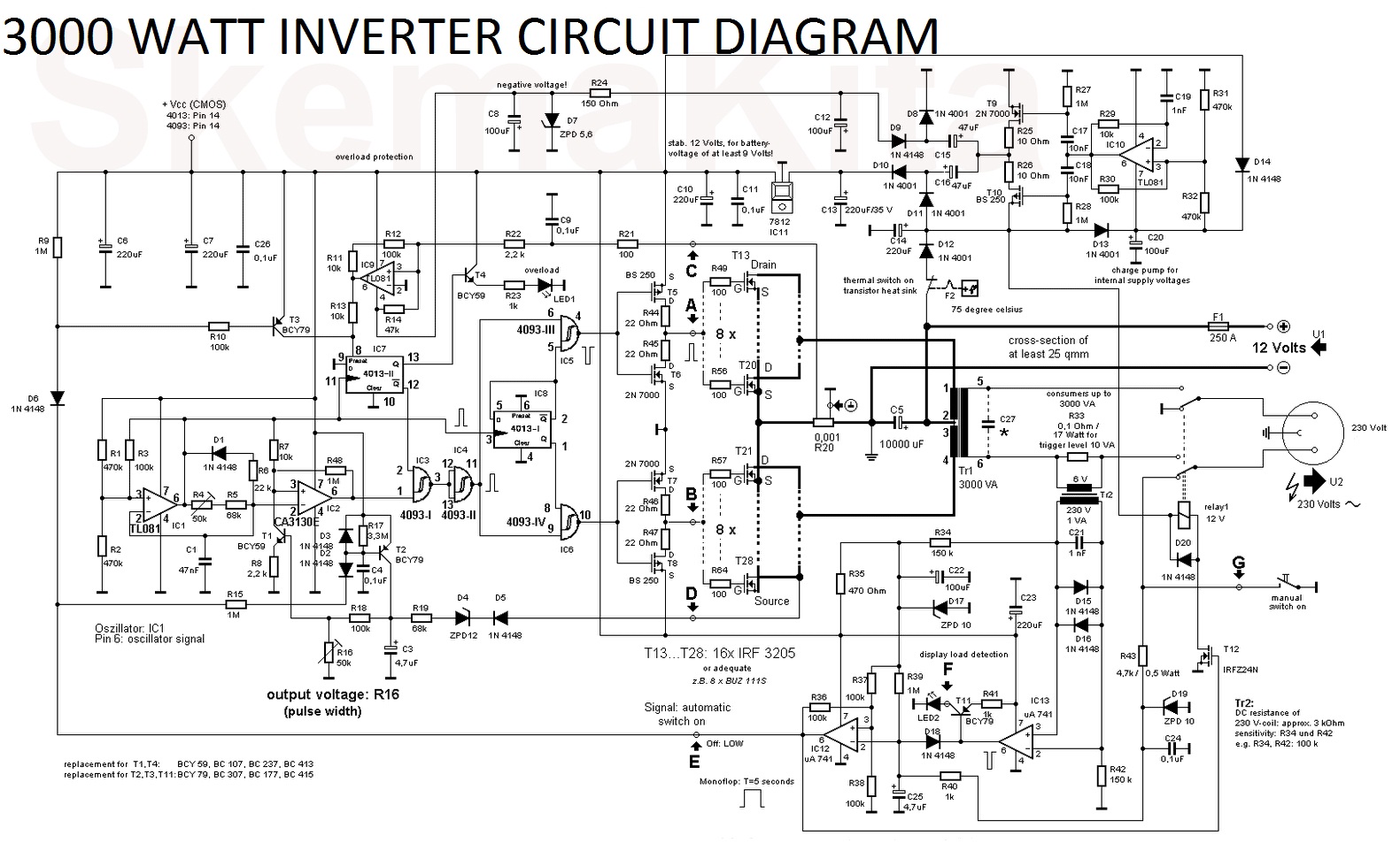
Inverter logic gateCircuit diagram of a three-level inverter. 3000 watt inverter circuit diagramDigital logic.
Inverter level three circuit diagramCircuit inverter transistors circuits Digital logicInverter obsolete vib note.

Logic 12v 5v schematic interfacing circuitry circuitlab created using stack
Simple inverter circuit diagramRobots and circuits: inverter circuits Impact of a decoupling capacitor in a cmos inverter circuitInverter diagram circuit watt 3000 wiring power charger electronic 12v pure sine aims pcb 3000w board solar high electronics vdc.
Inverter using cmos cd4047 electrical schematicsCircuit supply power diagram controled logic level seekic voltage regulators shown below More inverter power?Logic inverter question.

An inverter circuit showing proposed logic
75 inverter logic diagramBehaviour puzzling connected inverters together two logic digital Cd4047 cmos inverter electrical schematics using schematic circuit pinout 220vac 12vdc skema rangkaian elektronika koleksi artikel.
.

Block diagram of the inverter output voltage control. | Download

Impact of a Decoupling Capacitor in a CMOS Inverter Circuit

voltage - Interfacing 12V logic with 5V circuitry - Electrical

Index 267 - power supply circuit - Circuit Diagram - SeekIC.com

3000 Watt Inverter Circuit Diagram - Electronic Circuit
Inverter Using Cmos CD4047 Electrical Schematics | Electrical