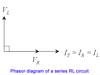
R L Circuit Phasor Diagram
Circuit rl series phasor diagram inductor assume Circuit rl phasor diagram series rlc resistor analysis examples voltage current phase electrical4u derivation value following Using phasor diagrams to evaluate series and true parallel rlc ac
Phasor Diagram for Series RLC Circuits - Wolfram Demonstrations Project
Jackng c. h. blog: series rl circuit (rev: 1.3) Phasor diagram for lrc circuit Rl circuit : working, phasor diagram, impedance & its uses
Phasor rlc parallel series ac circuits diagrams using true
Circuit phasor diagram rlc seriesSolved diagram represents phasor transcribed problem text been show has Series circuit rc phasor diagram vector impedance draw phase circuits power ckt voltages multiply why which capacitor finding when curveWhat is rl series circuit?.
Solved: use the phasor diagram for a parallel r?l?c circui...Phasor diagram of series rlc circuit the Series rlc circuit (circuit & phasor diagram)Phasor diagram for series rlc circuits.

Passive networks
Solved the diagram below represents the phasor diagram forSolved draw the phasor diagram for the circuit shown in Series phasor diagram circuit rl draw power ckt belowRl circuit : working, phasor diagram, impedance & its uses.
Phasor diagram parallel circuit current use figure following find part source solvedPhasor diagram circuit rlc combined networks passive Phasor diagram at r, l and c in ac -circuitPhasor rlc parallel rl translatorscafe impedance diagrams.

Solved:the phasor diagram for an rlc circuit is shown in flgure 24-38
What is rc series circuit? phasor diagram and power curvePhasor diagram rlc series demonstrations wolfram circuits Rl circuit : derivation, response factors, phasor diagram and its usesSeries rlc circuit analysis – all about electronics.
Rlc circuit phasor analysis impedance phaseCircuit phasor diagram rl parallel uses working its voltage relationship rc Rl phasor derivationPassive networks.

Phasor diagram circuit lrc
Phasor diagram of rl circuit / solved v figure 7 7 phasor diagrams ofSolved circuit phasor shown draw diagram transcribed problem text been show has Circuit diagram phasor rl series uses working its impedanceCircuit rlc series phasor diagrams electrical engineering.
.


RL Circuit : Derivation, Response Factors, Phasor Diagram and Its Uses

Phasor Diagram for Series RLC Circuits - Wolfram Demonstrations Project

JackNg C. H. Blog: Series RL circuit (Rev: 1.3)

Solved Draw the phasor diagram for the circuit shown in | Chegg.com

Series RLC Circuit Analysis – ALL ABOUT ELECTRONICS

Phasor diagram for LRC circuit - YouTube

Phasor Diagram of Series RLC Circuit The

RL Circuit : Working, Phasor Diagram, Impedance & Its Uses